My first big CNC project: An organizer rack for parts | ZDNet
Look, I made a thing (three things, actually).
David Gewirtz
This is so cool! I am unreasonably excited! I drew some diagrams on my computer. Hooked up a robot. Fed it a thick piece of plywood. And out popped a useful organizing rack.
I know that the concept of numerically controlled machines dates back amazingly far, but actually using my own CNC in my garage to make my own storage systems is bonkers-level cool to me.
I thought 3D printing felt like the future when that first MakerBot turned a roll of plastic filament into a tiny object. Since that first build, I’ve made custom 3D printed objects to solve all sorts of problems. But there’s a difference between making a 3D printed bracket out of plastic and making an entire cabinet out of wood.
And since this is my first real CNC project, well… wow!
For the rest of this article, I’m going to take you through the process. I’ll explain the problem I needed to solve, how I went about doing so, and what I learned from my first big run of the X-Carve CNC.
Also: Hands-on: Building the next generation X-Carve CNC (build log)
Problem statement
I’ve been trying to organize a lot of my small parts. These include things like screws and bolts, camera accessories and mounting adapters, electronic parts, and robot components. Last year, I decided to standardize on the
$10 Harbor Freight parts storage cases
two sizes
.

These are fine, until they’re no longer fine.
They work great for parts organization. I originally stored them on my shelves, on their sides. The only problem is that after some months, the weight of some of the heavier metal items began to deform the little storage boxes. They were also a bit difficult to take off the shelves, and when stored on their sides, some of the smaller items jumped from compartment to compartment.
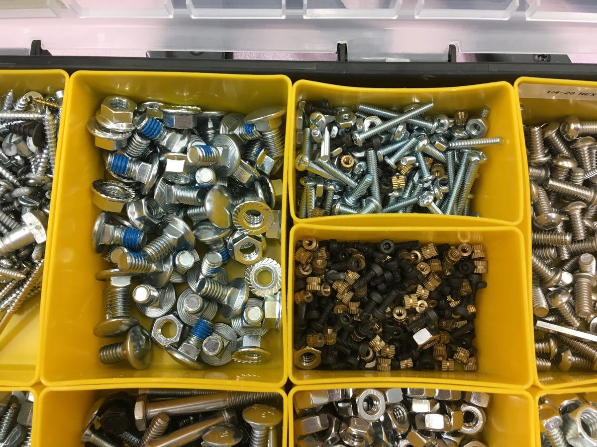
This will only get worse until I find a better way. And it’s not just for things like screws. Tiny electronic and robot components are getting mixed up, too.
What I needed was a storage unit that would let me store the storage cases flat. There are a lot of designs for this. But almost all of them involved precision measuring and precision woodworking, particularly with the table saw, and miter saw. I have both of those tools, but I wanted to use the CNC because I thought it would be cool to have a robot do the bulk of the work from something I designed on my computer.
Before I go on, I want to credit The Internet for most of this design. I found measurements in one video, a rough design in another, the idea for the curved front sliders in another. Unfortunately, I didn’t keep track of where I found these resources. I mostly just noodled on the project for a month or so. But I can’t take credit for this design. Makers out there was my inspiration.
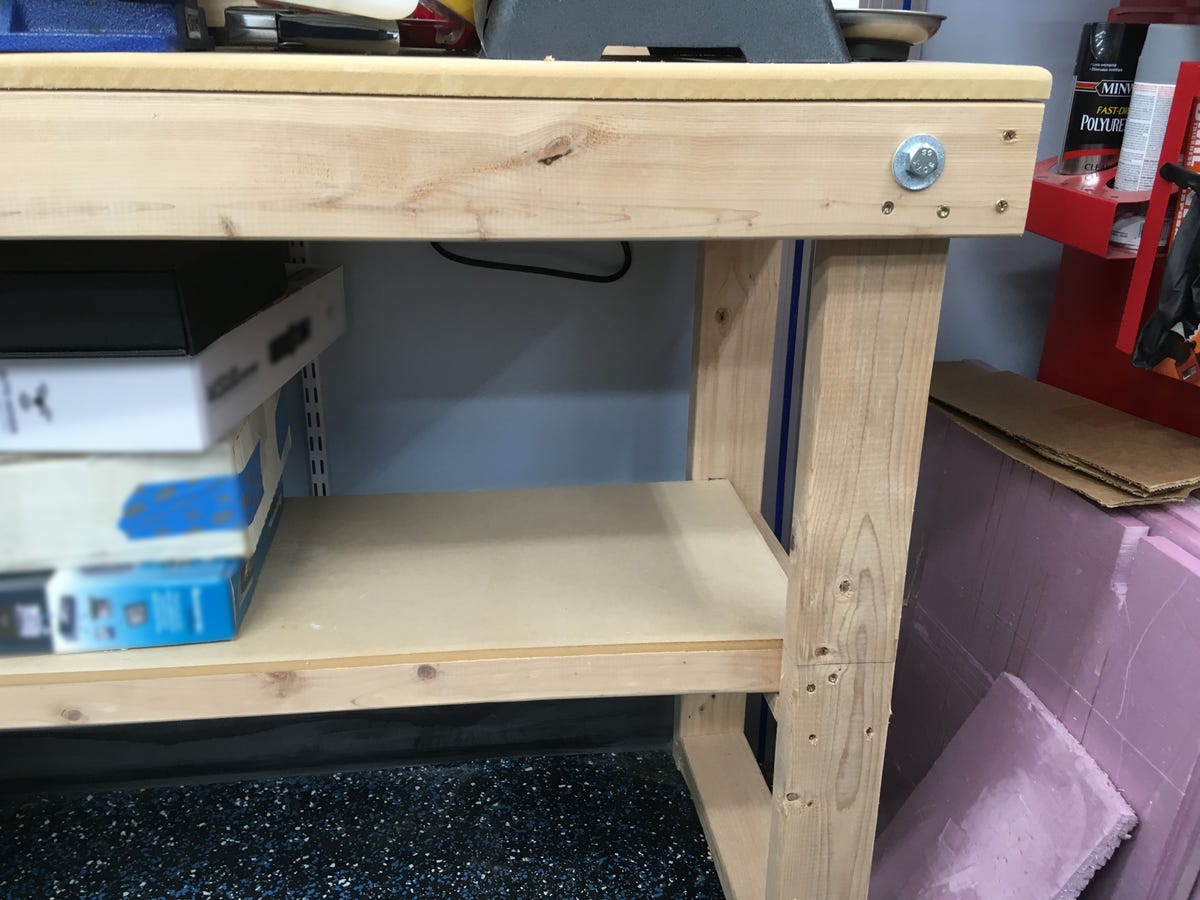
Desktop fabrication allows you to custom build solutions for your unique space constraints.
My limits were simple. I needed each rack to fit on a lower shelf of my workbench. That determined the maximum height, which turned out to be a skosh under 14 inches. 14 inches would be enough to store five of the smaller plastic storage cases or one big case and three smaller cases.
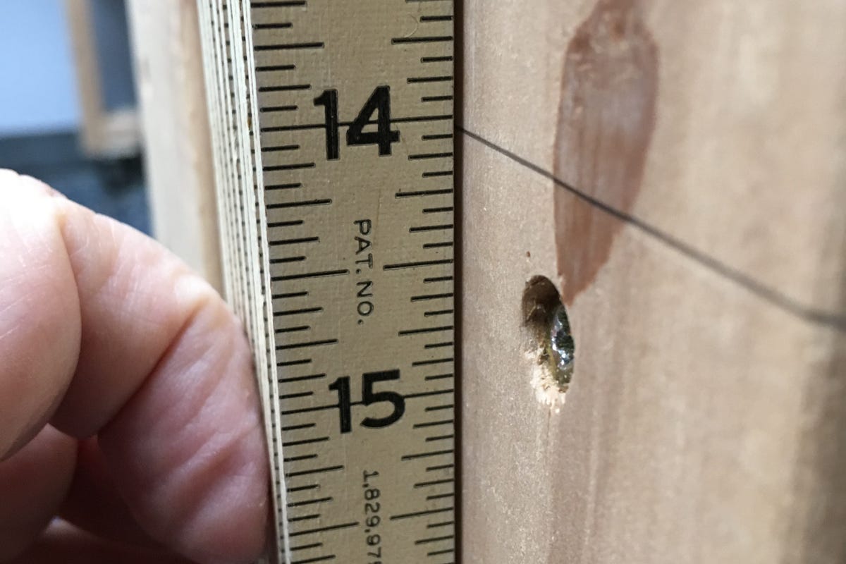
I was just barely able to fit five cases, plus a top and bottom, in the available space.
Given the width of the storage cases and of my workbenches, I can fit three racks under one bench. But first, I had to build them.
Design
To put the racks together, I first mocked them up using SketchUp. I’m quite familiar with SketchUp and creating a mockup allowed me to visualize what I’d be producing.
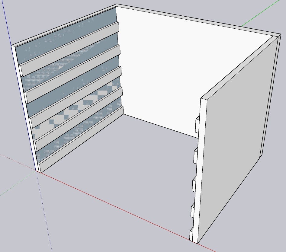
My first prototype design was in SketchUp
I didn’t use the SketchUp document as the actual source set of plans sent to the CNC. Instead, I used Easel, the design and control tool that comes with the X-Carve. Easel is also available for use with other CNC machines, so you’ll hear about it more as I test additional machines.
In 3D printing, we usually use a CAD program like Fusion 360 or Tinkercad to generate a design, which is then saved off as an .STL file. That .STL file is then brought into a slicer (like Cura), which interprets the CAD design and generates the gcode that actually drives the machine.
You can use Fusion 360 to create CNC designs as well, but while I’m pretty comfortable using Fusion 360 to design 3D printable objects, there are different considerations for subtractive manufacturing (CNCs cut out, 3D printers add on). I just haven’t gotten there yet. I expect to take on Fusion 360 for the CNC once I become more comfortable with the CNC.
For this project, I just used Easel, which also generates gcode. I had a 2-foot by 4-foot piece of 3/4-inch plywood in my workshop, so I decided to design for that. I only had one sheet, so I had to adjust elements of my design to fit that sheet. In particular, I didn’t make a full-size back or top but instead used plywood strips. That way, I was able to cut the first of three storage racks out of that one sheet.
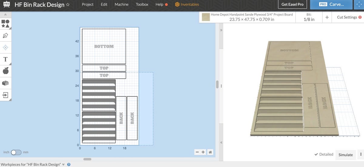
I machined this design in two parts, rotating the wood panel between each part.
This actually proved to be a pretty interesting constraint because when it came time to make the second and third rack, all I needed to do was get two more
2×4 foot project boards from Home Depot
. I knew an entire rack could be built from each.
I really like the idea of storing my plans in the cloud and then sending them to the robot in my workshop to turn them into physical objects. I’ve done this for the past few years with plastic objects, but now I’m making real wooden storage units using the same “store it in the cloud” benefit that comes from desktop fabrication.
Easel lessons
Nearly all design programs allow you to manage your work in layers. Bring to Front and Send to Back commands move a layer all the way to the top or bottom. Bring Forward and Send Backward move in the specified direction one layer at a time.
Layers also exist in Easel. Each layer not only specifies a shape to carve but the depth to carve as well. My design instructed the CNC to carve two 1/4-inch pockets. It also instructed the CNC to carve the full 3/4-inch plywood to separate the components from the master sheet of plywood.
However, it turns out that the topmost layer “owns” the depth instruction. So if you have a line that instructs the CNC to carve 3/4-inch deep, but it’s under a square that instructs the CNC to carve 1/4-inch deep, the CNC will only carve 1/4-inch. I made that mistake. Once I moved my perimeter lines to the top layer and set them at 3/4-inch, the problem was solved.
Shoutout to the Facebook X-Carve Users group for helping me find that answer.
I also found that using the absolute value shape position fields for each object helped me precisely layout my cut pattern. I based those offsets on my original design in SketchUp, just translating distance from the origin for each object to be cut.
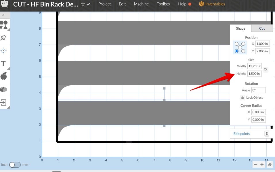
This works well for items with fixed spacing.
Finally, I found that by customizing depth per pass and feed rate, I was able to reduce my subsequent carves from nine hours to four. Your depth per pass (how much the cutter takes off at a time) should never be more than half the thickness of your bit. I’ve been using a 1/8-inch bit (0.125-inches), so my max depth per pass was 0.0625-inches. Apparently, my math was slightly off because I ran at 0.064, but it still worked. This was twice as deep as my first run, which was the default, set at 0.032-inches.

Here’s where I increased the cut depth, reducing the number of passes by half.
Zoom is your friend
Over the years, I’ve learned that robotic manufacturing devices fail in the most creative ways. Usually, the project gets messed up, but sometimes it’s worse — there could be overheating, fire, or some other hazardous result. It’s not quite a robot uprising, but unattended robots can be dangerous.
But 3D prints can take days. My engine block print took a week. While it might be fun to bring the La-Z-Boy into the Fab Lab or workshop, it’s not practical. The CNC can also be very, very loud. Running the CNC and the dust collection system cranks the room up to 83 dB. That can be painful, and long exposure could cause damage to your ears.

My Apple Watch says it gets loud in the workshop with the CNC running.
The next best thing is to hook up a camera and monitor it remotely.
For the 3D printers, I use Raspberry Pis with OctoPrint. OctoPrint has a mode specifically for operating a webcam. Easel, for the CNC, does not. But since the
Asus Zenbook Duo UX482
with Windows 11 was controlling Easel, I had a full Windows machine available to me. Once again, a big shout-out of thanks to Asus for providing the project computer for use with these CNC projects.
And, hey, Zoom. Why not? I have a paid-for Zoom license, which allows very long web conferences. I set my monitoring conference to 10 hours.
The Zenbook Duo
does have a built-in webcam, but I would have had to face the whole computer at the CNC, which would make it impossible to control Easel. Instead, I mined my junk bin and found an old webcam, hooked it up, and pointed it at the CNC.
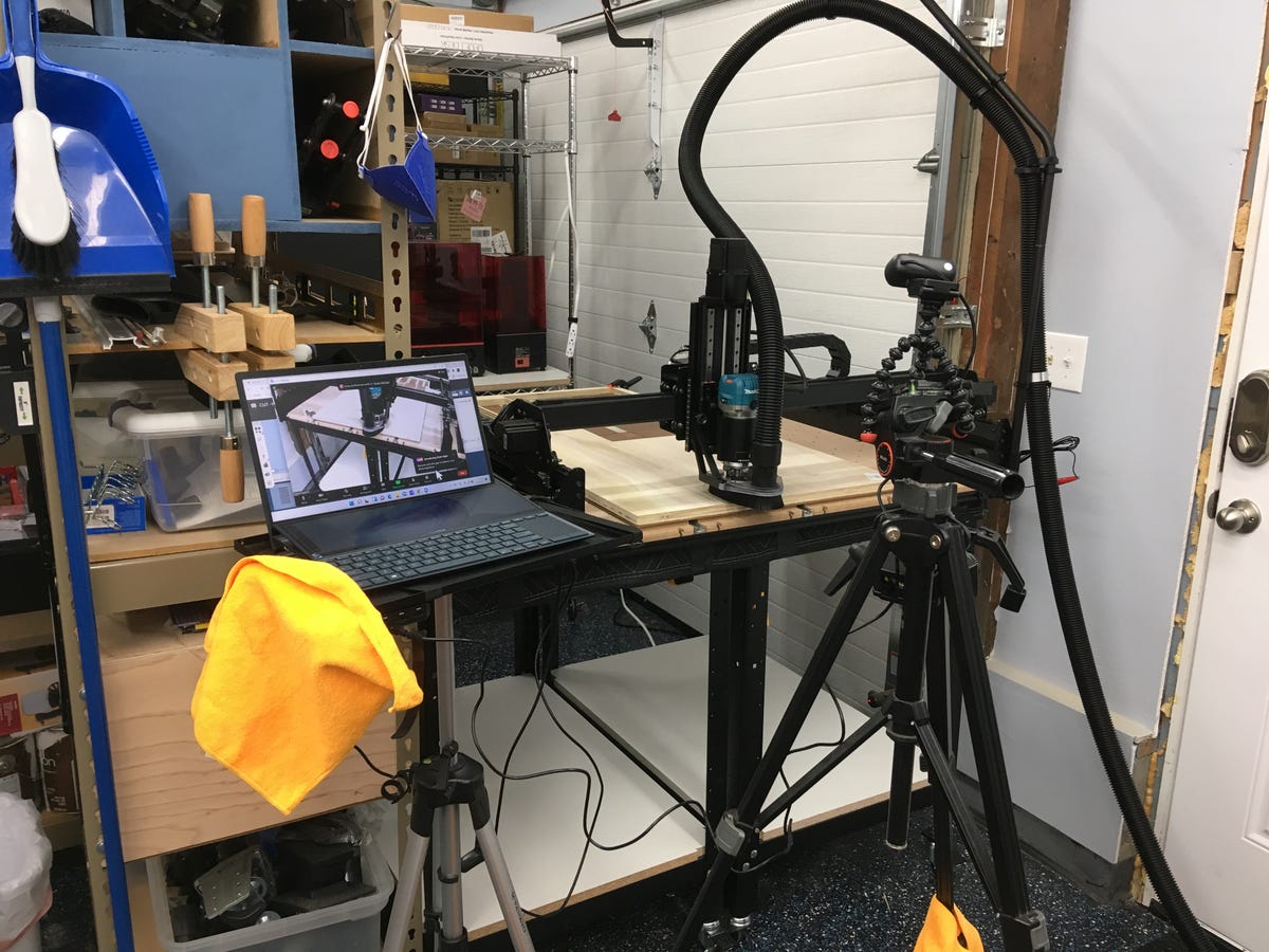
You can see the webcam, the control computer, and the CNC, all working together.
My CNC work area is right on the path from the house to the cars, so that orange cloth is there to keep us from bumping into the computer while running to and from the carport.
I launched Zoom on whatever computer I was working at while the CNC was running and had a good view of the entire process. It’s good that I did because, at one point, there was a failure that had the spindle spinning a chunk of wood wildly around the cutting surface. It turned out that a ply from the plywood wasn’t properly glued down at the factory, and it just came loose. I got to press the big red emergency button for the first time. It was very satisfying.
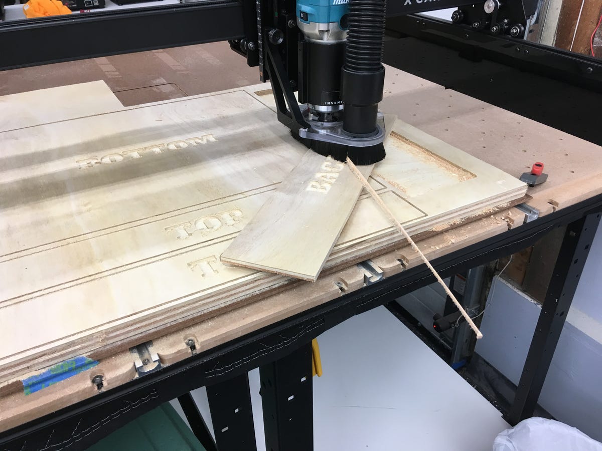
This is an example of why you need to keep an eye on your robots.
No harm. No foul. The project worked out anyway.
Small scale production
I had three racks to make. I learned a bunch of lessons between each unit. The biggest challenge was what the CNC world calls “hold-downs,” or keeping your material from moving. Whether it’s making sure your plastic stays stuck to the build plate on a 3D printer, your vinyl stays in place on a vinyl cutting machine, or your wood doesn’t budge on a CNC, keeping material from moving is a common challenge in desktop fabrication.
When I bought the CNC, I bought a bunch of clamps. But I discovered that clamps don’t always work because they might get in the way of the spinning bit. I had pretty tight tolerances on my plywood sheets, so clamps could only be placed in a few places.
I also tried double-sided tape, but I misunderstood the weight dynamics. My available surface for cutting is 1000mm x 1000mm, or 39.37 inches. The boards were 48 inches, and so there was a fair chunk of wood hanging off the back of the CNC.
When the weight of the wood is distributed across the entire sheet of plywood, the board lays flat. But as you cut out large squares at the front, the center of gravity moves back on the remaining board. This caused the board to tilt at the back and lift up in the front. Physics. It’s not just for classrooms anymore.
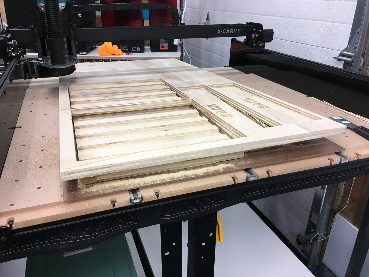
So, yeah, that happened.
By my third unit, I figured out how to mix clamps and double-sided tape, and the third unit cut without any mishap at all.
In this picture, you can see how the entire rack unit fits on one project board.
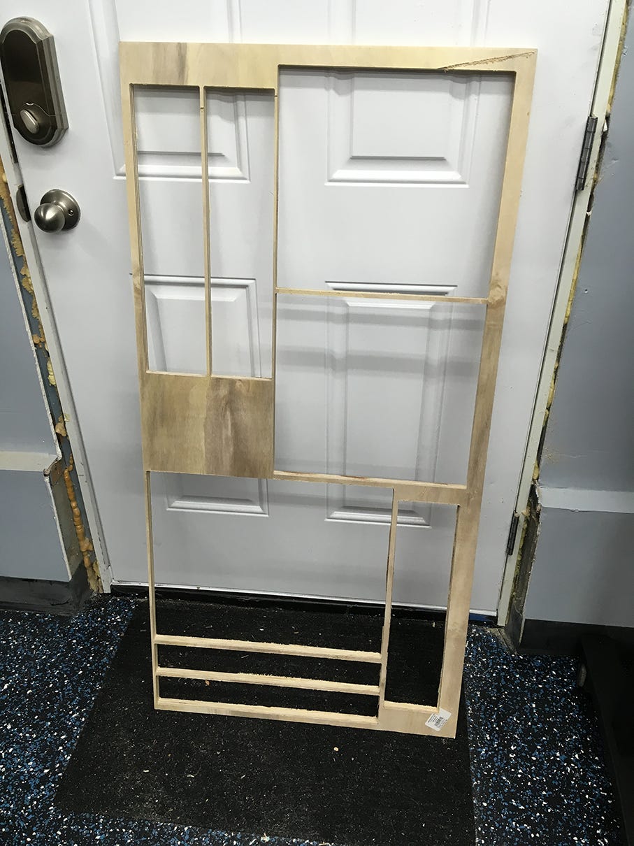
This carcass shows how all the components fit nicely on one project board and all the cuts the robot made while I worked on other projects.
Here’s a clear picture of the rack side supports. The CNC carved all the lower areas, as was the board itself. There’s no way I could achieve that level of precision with traditional woodworking tools.
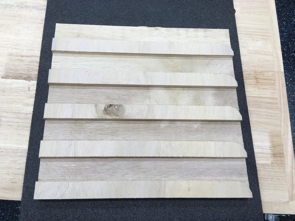
These side panels took the most time, because the wood had to be cut away to make the side rails.
Here are some of the cross-members. To carve in the letters, I just typed them into Easel, just like you’d type text into PowerPoint or Photoshop.
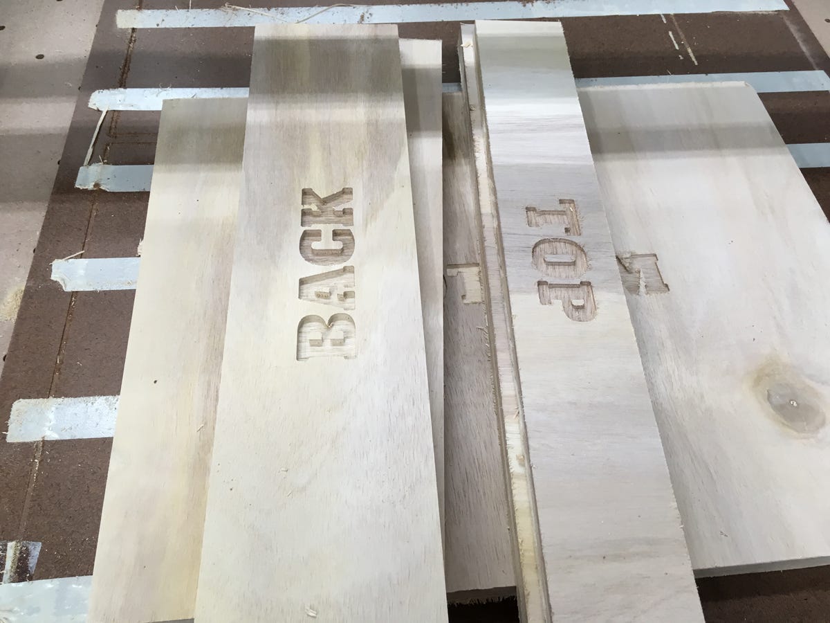
A very large segment of the CNC market is devoted to sign-making. I just used the lettering capabilities to mark my pieces.
I labeled the boards, mostly so I knew what would go where on the project, but also to see how doing something like lettering would work. Some of the letters got fuzzy in subsequent carves, and I had to clean them out with a wire brush. I think my bit got pretty dull after carving out three full storage units. For the record, I used a 1/8-inch dual-flute straight bit. You can get them for just a couple of bucks, so they’re clearly consumable, and I should probably buy some more.
Assembly
Assembly was relatively straightforward. It required glue, some clamps, and some brad nails. The most annoying process was sanding. As the bit got duller, the amount of sanding I had to do increased. If that’s not an argument for buying new bits, I don’t know what is!
Here, you can see quite clearly how the carved-out rail system holds the Harbor Freight storage cases.
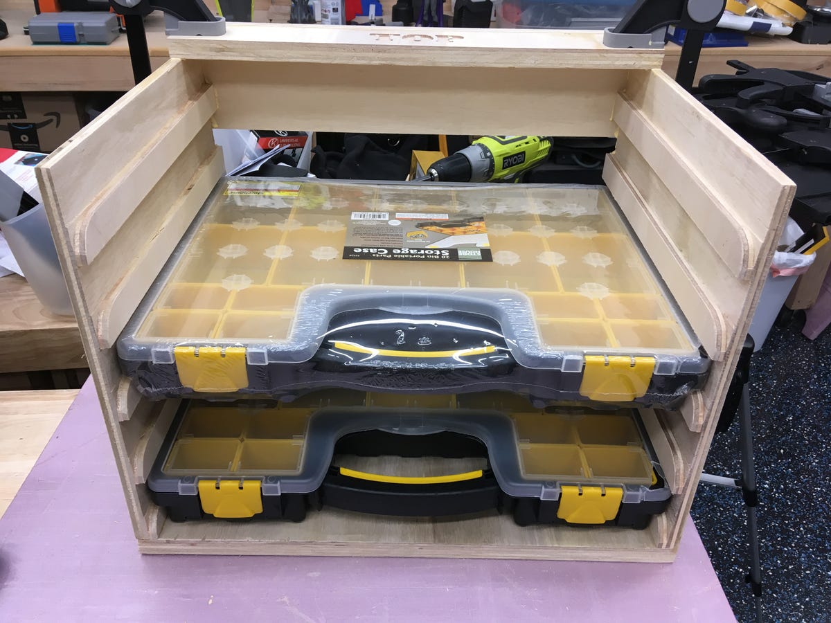
You can really see how the carved rails support the storage cases here.
This next picture is similar. It shows how I used cross-strips, instead of a full top and back, in order to fit all the pieces onto one plywood project board.
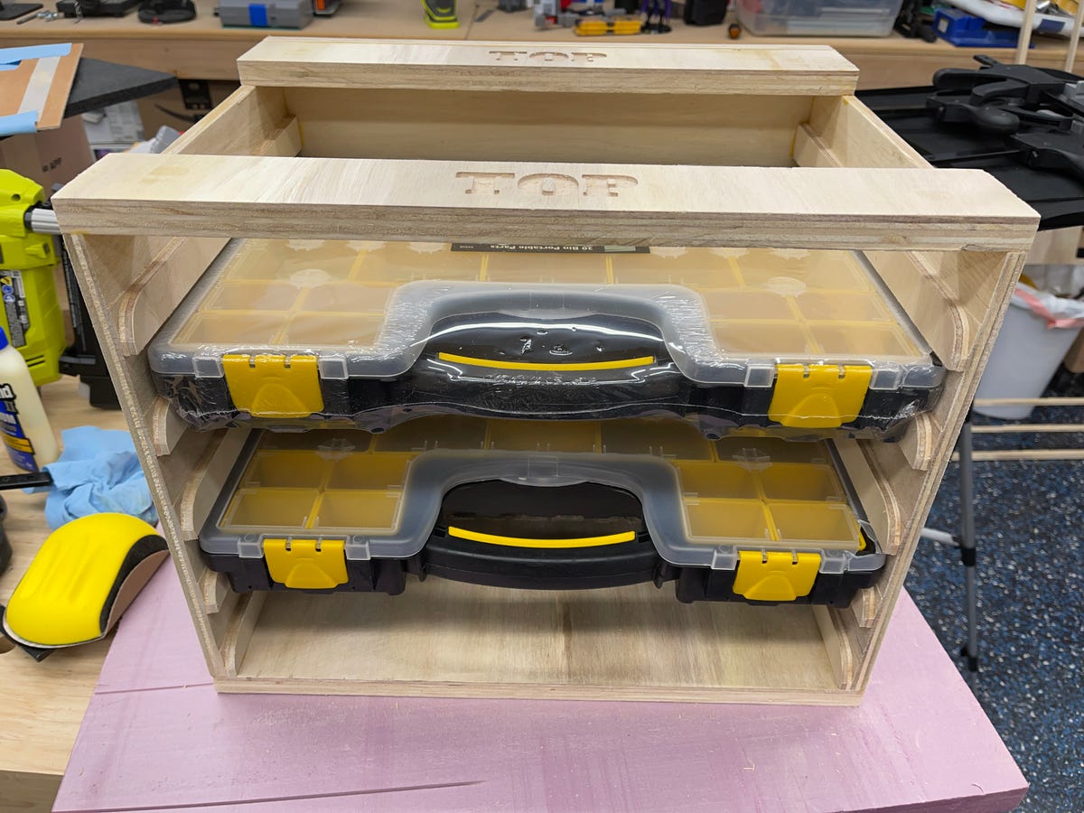
Each unit took about an hour to assemble. I left them overnight to let the glue set. And then they were done.
Final thoughts
I think this might be game-changing for me, and it might be for you, too. If you’re reading this here on ZDNet, there’s a good chance you’re super-comfortable with software. You, like me, might not be as comfortable with power tools.
Desktop fabrication allows you to create custom solutions to home and work problems. I’ve talked about this a lot with 3D printing. I’ve 3D printed many custom solutions for my studio, my projects, my wife, and just for around the house — things that improve productivity and make life easier.
My garage workshop is a work facility. It’s where I do many of the projects and shoot many of the videos I need to make my living. But it’s a finite space, and it’s small. It’s wide enough for two cars, but it’s not deep enough to fit most cars into it. The previous homeowner ate into the garage space to put in a laundry room and guest bathroom, so unless you drive a MINI Cooper, you’re not putting a car in that space.
The key issue for me is how to optimize that space. There’s very little real, workable space left with all the gear I have for work. This has fostered clutter, which I’m slowly beating back with organizational systems.
You’ve seen me build organizational systems for managing cables, for increasing shelf space, and for managing 40+ USB devices. Each of these solutions used some combination of CAD, 3D printing, and laser cutting. For my small parts and components, this newest organisational system still uses CAD, but this time with a CNC.
Desktop fabrication isn’t just for factories, startups and product designers, and hobbyists. These tools can be powerful for offices and professional settings because they solve problems and provide solutions that are customized for your individual needs. Yes, there’s a learning curve, but everything worth doing does take a little work.
As for me, I can’t tell you how pumped I am to have three new storage racks, to have solved my small parts challenge, and to have done so with the help of a CNC.
Stay tuned for my next project. And what about you? Have you made anything with a CNC or 3D printer? Tell us about your builds, any lessons learned, and any tips you might have in the comments below.
You can follow my day-to-day project updates on social media. Be sure to follow me on Twitter at @DavidGewirtz, on Facebook at Facebook.com/DavidGewirtz, on Instagram at Instagram.com/DavidGewirtz, and on YouTube at YouTube.com/DavidGewirtzTV.
For all the latest Technology News Click Here
For the latest news and updates, follow us on Google News.
